Wedge Barriers Fundamentals Explained
The Basic Principles Of Wedge Barriers
The Basic Principles Of Wedge Barriers
g., springtime support 65 )may be taken care of to the end of the spring pole 58 to allow compression of the springtimes 60. As the springs 60 are pressed between the springtime supports 62, the springtime assembly 54 generates a pressure acting on the camera coupled to the springtime pole 58 in an instructions 66. The staying pressure applied to
the cam web cam deploy the wedge plate 16 may might provided offered an electromechanical actuator 84 or other various other. Because of this, the springtime assembly 54 and the actuator 84(e. g., electromechanical actuator)may run together to equate the web cam and lift the wedge plate 16.
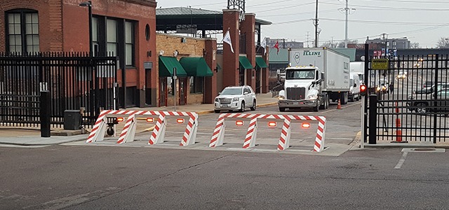
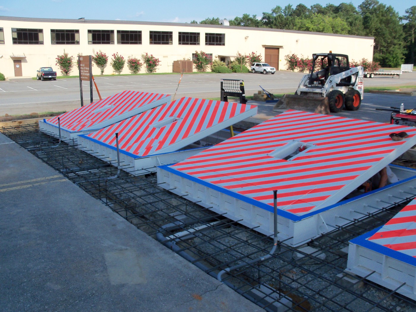
As pointed out over, the spring setting up 54 puts in a continuous pressure on the web cam, while the electromechanical actuator may be managed to apply a variable pressure on the web cam, thereby making it possible for the training and decreasing( i. e., releasing and withdrawing )of the wedge plate 16. In certain personifications, the continuous force applied by the spring assembly 54 may be flexible. g., electromechanical actuator) is disabled. As will be appreciated, the spring assembly 54 may be covered and secured from debris or other elements by a cover plate(e. g., cover plate 68 received FIG. 4) that may be significantly flush with the elevated surface area 38 of the structure 14. As pointed out over, in the released setting, the wedge plate 16 offers to obstruct gain access to or More Bonuses traveling beyond the barrier 10. For instance, the obstacle 10(e. g., the wedge plate 16 )might block pedestrians or lorries from accessing a building or path. As talked about above, the barrier 10 is affixed to the support 30 protected within the foundation 14,
front braces 71. As an outcome, the linkage assemblies 72 may pivot and turn to make it possible for the collapse and extension of the affiliation settings up 72 throughout retraction and deployment of the bather 10. The linkage assemblies 72 reason activity of the wedge plate 16 to be limited. For instance, if a vehicle is traveling towards the released wedge plate 16(e. For instance, in one condition, the safety legs 86 may be extended throughoutupkeep of the obstacle 10. When the security legs 86 are deployed, the safety legs 86 support the weight of the wedge plate 16 versus the surface area 12. Because of this, the training device 50 might be shut off, serviced, eliminated, changed, and so forth. FIG. 5 is partial viewpoint view of an embodiment of the surface-mounted wedge-style barrier 10, illustrating the cam 80 and the cam surfaces 82 of the training device 50. Especially, 2 webcam surfaces click here for more 82, which are referred to as reduced camera surfaces 83, are positioned listed below the web cam 80. The reduced camera surfaces 83 may be fixed to the surface 12 (e. As an example, the reduced webcam surfaces 83 and the placing plate 85 helpful hints might develop a solitary item that is protected to the anchor 30 by screws or other mechanical bolts. Furthermore, two camera surfaces 82, which are described as upper cam surfaces 87, are positioned over the camera 80 and coupled to (e. In various other embodiments, intervening layers or plates might be positioned in between the surface 12 and the reduced webcam surfaces 83 and/or the wedge plate 16 and the upper web cam surfaces 87 As mentioned over, the webcam
80 converts along the camera surfaces 82 when the wedge plate 16 is lifted from the retracted position to the released position. In addition, as stated over, the springtime assembly 54 (see FIG. 3 )may offer a force acting upon the cam 80 in the instructions 102 via spring pole 58, which may lower the force the electromechanical actuator 84 is called for to relate to the camera 80 in order to activate and lift the wedge plate 16. 1 )to the released position(see FIG. 4). As shown, the web cam 80 includes track wheels 104(e. g., rollers), which call and equate along the web cam surfaces 82 during procedure.